TM-55-2350-224-14 - Page 54 of 57
TM 55-2350-224-14
APPENDIX E
DETAILED PROCEDURES FOR SECURING THE M577/A1/A2 REAR RAMP DOOR
E-1.
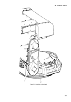
Follow these procedures until new rear tiedown provisions are installed on the underside of the
carrier:
a. Before shipping M577’s, put the canvas and poles that are normally stored on the outside rear of
the carrier inside the carrier.
b. Make sure the latch mechanism that holds the ramp closed is fully engaged. Units may have to use
a crow bar or some other tool to force the latch down.
c. Tighten the lock nut above the latch.
d. Drive a wedge (wooden or scrap metal) into the area above the latch, to ensure the latch stays
down.
E-2.
As an added safety precaution during tiedown and shipment, MTMCTEA recommends units follow
the procedures given in steps 1 through 3 below. This requires two, approximately 160-inch long, l/2-inch
IRWC cables and sixteen 5/8-inch cable clamps (per vehicle). The word “deck” in paragraphs 1-3 below
refers to a railcar, airplane, trailer, or ship deck.
a. Before securing the carriers run a l/2-inch IWRC cable (minimum diameter) horn the left rear
tiedown provision to the right rear lifting provision and another from the right rear tiedown provision to
the left rear lifting provision. Secure these two cables, leaving slack in the cables. They will form an “X”
on the rear of the carrier. (This will keep the ramp horn falling on someone who is connecting the chains
from the deck to the carrier.)
b. Connect the tiedown chains/cables from the deck to the tiedown provisions. (Do not leave slack in
the chains.)
c. Tighten the two cables on the carrier to remove the slack. This allows the tiedown shackles to hang
in the correct orientation (an angle less than 600 from the horizontal).
E-1
Back to Top

