TM-55-2350-224-14 - Page 47 of 57
TM 55-2350-224-14
APPENDIX D
REQUIREMENTS FOR CONVERTING THE M981 , M901 , M901A1 (lTV) LAUNCHER
FROM STANDARD TO TRANSPORT CONFIGURATION AND BACK TO STANDARD
This appendix is extracted from the M901 (ITV) system specification. Everywhere the M901 is
cited, the information applies to the M901A1 and M981. If an M901 vehicle is already in the
transport (or “low stow”) configuration, follow the procedure in paragraph 6 to reduce the vehicle
height for transport in C-130 or C-141 aircraft. However,
if the M901 is in the standard
operational (or
“high stow”) configuration, perform all the steps in this appendix through
paragraph 7. See TM 9-2350-259 or TM 9–2350-266 series for reference.
To reduce the M901 vehicle overall height for transport, proceed as follows: Place launcher in erect
position. Bleed system down in accordance with paragraph 1. Remove stowage brackets in accordance
with paragraph 2, and proceed through paragraph 8.
D-1. Hydraulic Pressure Bleed-Down Procedure:
a.
Apply power to turret in the normal manner, to place launcher in erect position at 1800 azimuth
(facing rear).
b.
Set EMER PWR switch to UP POSITION.
c. Move hand controller up and down in elevation until launcher ceases motion.
d.
Set TURRET POWER switch to OFF, and then set EMER PWR switch to OFF.
e.
Ensure that ERECTION LOCKS are engaged. If not, repeat steps a through d to ensure erection
locks remain engaged.
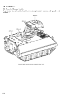
f.
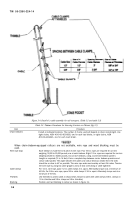
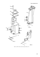
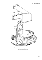
Support front of launcher, using two C-clamps (NSN 5120-00-203-6431) and two 2x4 lumber
bracing, as shown in figure D-1.
Figure D-1. M901 hydraulic pressure bleed-down
D-1
Back to Top

