TM-55-2350-224-14 - Page 43 of 57
TM 55-2350-224-14
e.
Secure the battery.
f.
Inspect engine, brakes, and tiedowns, to en-
sure they are in good mechanical condition.
g.
Mark shipping weight and center of balance
location on both sides of the carrier.
5-7-2. Specific Carrier Preparations for Airlift:
a.
M106, M106A1, and M106A2. Secure
base plate for the 107-mm mortar inside
carrier.
b. M548 and M548A1.
Secure the bows
canvas inside the carrier.
c.
M577, M577A1,
and M577A2.
Remove
antenna extensions and guards to reduce
the
the
and
the
the
carrier to its lowest configuration. Rear ramp
requires special preparation to prevent it from
falling during transport. See appendix E for in-
structions.
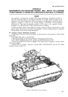
d. M901, M901A1, and M981.
Reduce the
height of the carrier for transport on the C-130
and C–141 aircraft by removing the armored sight
cover from the top of the TOW launcher or
targeting head. The wide field of view (WFOV)
sight must also be removed (by a qualified fire-
control technician). Appendix D contains detailed
procedures for converting from the high stow to
the low stow position.
e.
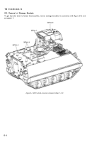
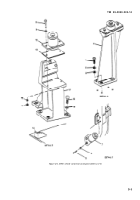
M1068. Remove the antenna extensions and
guards, auxiliary power unit, and tent light set
mounts to reduce the carrier to its lowest configu-
ration.
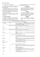
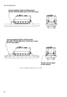
5-7-3. Loading Instructions
a.
Metal parts of the carrier tracks must not
make contact with the aircraft loading ramp or
cargo compartment floor. Prolonged operation of
vehicles causes the rubber track pads to chip,
crack, and wear, thus eliminating the rubber pad
protection and allowing the steel track shoes to
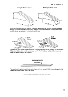
impact the surface. Therefore, the use of shoring is
always required when loading and offloading the
carriers. Use 2- by 12-inch lumber to provide two
rows of shoring 24 inches wide and spaced to
match the carrier tracks. The loaded height of the
carriers may be reduced slightly by use of 3/4inch
or 1/2-inch plywood shoring instead of 2- by 12-inch
lumber. Lay the shoring from the ground end of
the aircraft ramp extension into the cargo com-
partment, so that when the carrier is in the
tiedown position, the tracks are on the shoring.
Shoring is provided by the transported unit or by
the shipping activity.
b.
Place the transmission in neutral and set the
parking brake, after the carrier has been posi-
tioned aboard the aircraft.
c.
Restraint factors (g loads) for minimum ac-
ceptable conditions (specified for crew and passen-
ger safety in the event of a controlled emergency
landing) are specified in the applicable aircraft
Technical Orders (TO 1C-5A-9, TO 1C-130A-9,
and TO 1C-141A–9).
d.
For the M113A3 and M730A2, put the trans-
mission in SL position.
5- 2
Back to Top

