TM-55-2350-262-14 - Page 30 of 42
TM55-2350-262-14
CHAPTER 6
MARINE AND TERMINAL TRANSPORTABILITY GUIDANCE
Section I.
6-1. Scope
This chapter provides marine and terminal trans-
portability guidance for movement of the M9 ACE.
It covers technical and physical characteristics, as
well as safety considerations, and prescribes the
materials and guidance required to prepare, load,
tie down, and unload the vehicle.
6-2. Safety
Besides the safety precautions contained in chap-
ter 3, the following areas apply:
a. All vessel equipment and gear should be
inspected before use.
b.
All stevedore slings and other items used in
loading and unloading operations should be
checked for their condition and capacity.
c. All other precautionary measures and safety
regulations peculiar to the loading/unloading site
or terminal will be observed.
d.
Vehicle fuel tanks must be drained and bat-
GENERAL
tery terminals disconnected.
e. Vehicle transmissions must be placed in the
neutral position and handbrakes must be set.
NOTE
When the M9 ACE is loaded on vessels
that are adequately ventilated by power
blowers, such as those commonly found on
the roll-on/roll-off (RORO) ships, fuel
tanks need not be drained.
6-3. Water Shipment
The M9 ACE can be transported by a great variety
of inland waterway cargo carriers, lighters, and
barges and by all seagoing cargo vessels.
NOTE
The methods described in this chapter for
lifting and securing the M9 ACE are
suggested procedures. Other methods of
handling and stowage may be used to
accomplish safe delivery without damage.
Section Il. LOADING AND SECURING
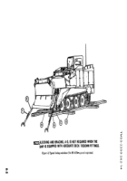
6-4. General Rules for Stowing
a.
General.
Whenever possible, vehicles should
receive the protection of below-deck stowage. In
general, good stowage of vehicles means having
them placed fore and aft as close together as
practical, with minimum spacing (about 4 to 6
inches) between outer vehicles and the sweat-
boards. Breakable parts or auxiliary equipment of
the vehicles should be adequately protected and
secured for shipment. If not shipped on the vehicle,
spare parts and on-equipment material should be
properly identified as to location or disposition
during shipment.
Vehicles in the ship’s hold
should be blocked in front, in rear, and on both
sides of the wheels so that the vehicles cannot
move. Individual vehicle blocks should be braced
to bulkheads, stanchions, and other vehicle blocks.
In addition, all vehicles should be lashed with wire
rope or chains to nearby padeyes, bulkheads, or
stanchions.
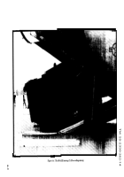
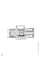
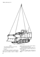
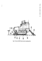
b. Lifting.
Correct lifting points on the vehicle
are the lifting eye provisions atop each of the four
extreme corners of the hull’s superstructure as
shown in figure 6–1.
c. Loading.
A check must be made to ensure the
hatch girder clearance of the specified vessel is at
least 107 inches (272 cm) for the unreduced M9
ACE or 98 inches (249 cm) for the reduced M9
ACE (cupola and exhaust stack removed). The
vehicle can be loaded over the beach or from piers
onto landing craft, beach discharge and amphibi-
ous lighters, landing ship tanks (LST), and landing
ship docks (LSD), under its own power or by crane
of adequate capacity. The vehicle can also be
loaded under its own power onto the deck of
barges from pierside when tidal conditions are
favorable and ramps are available. The vehicle can
be loaded onto seagoing vessels by shoreside or
floating cranes of adequate capacity. Jumbo booms
and heavy-lift ship’s gear may be used to load the
vehicle onto vessels. Also, the vehicle can be
driven or towed onto RORO vessels. Since the M9
ACE is amphibious, it can, under favorable condi-
tions, swim aboard, or debark from, offshore LST
and LSD. However, extreme caution is necessary
during amphibious operations because loss of free-
board may occur from excessive waves or while
turning on the water.
6-1
Back to Top

