TM-55-2350-262-14 - Page 24 of 42
TM55-2350-262-14
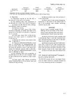
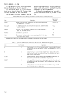
Preparation*
Loading
Offloading
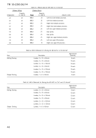
Operation
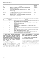
Type Aircraft
(Personnel/Minutes)
(Personnel/Minutes)
(Personnel/Minutes)
(Personnel/Minutes)
C-130 and C-141
2/120
6/60**
6/10
6/100
C-5
2/30
2/40**
2/10
2/30
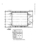
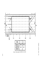
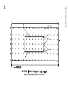
*Preparation time does not include fabrication of shoring.
**This
time
may
vary, depending on how long it takes the vehicle to settle on sleeper shoring.
d. Preparation.
(1) Preparation required for the M9 ACE is
the same for C-130 and C–141 aircraft.
(2) The following steps cover preparation of
the M9 ACE for C–130, C–141, and C–5 transport:
(a) Inspect the M9 ACE for leaks, damage,
and operation; repair as required.
(b) Fabricate shoring.
(c) Check fuel level. Drain (TM 5-2350-
262-20) as necessary to reduce fuel level to 25
percent for C-130 and C-141 aircraft or 75 percent
for C-5 aircraft.
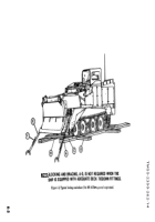
(d) Fold dozer blade (TM 5-2350-262-10).
Ensure the lower apron is installed (TM
5-2350-262-10).
(e) Remove the antenna and antenna base
(TM 11-5820-401-1).
(f) Place the SPRUNG/UNSPRUNG control
lever in UNSPRUNG for loading/offloading. Re-
duce the track tension (TM 5-2350-262-10) until
the track lies directly on top of road wheel four,
relieve the hydraulic pressure (TM 5–2350–262–
10), and place the SPRUNG/UNSPRUNG control
lever in SPRUNG for flight.
(3) The following steps cover preparation of
the M9 ACE for C–130 or C–141 transport. Refer
to TM 5–2350-262-10 for location of major compo-
nents.
(a) Place eight cargo tiedown assemblies
(FSN 1670-00-937-0271) in the vehicle bowl and
interlace D-ring to D-ring.
(b) Remove vehicle’s rear door and place it
in the vehicle bowl.
(c) Place a piece of pad, energy dissipating,
honeycomb, in the bottom of the vehicle bowl. If
this is not available, other suitable cushioning
material may be used.
WARNING
Driver’s hatch assembly weighs 900 lb
(408 kg). D
O
not put hands or feet under
driver’s hatch assembly while removing or
installing hatch. Severe injury may result.
(d) Remove the driver’s hatch assembly (TM
5-2350-262-20). Place it and the mounting hard-
ware, with latch forward, in the center of the bowl.
Tape over the eight vision blocks.
(e) Remove the apron and dozer blade exten-
sions (TM 5–2350–262–20). Tape mounting hard-
ware into the holes in the apron and dozer exten-
sions. Place the apron and dozer extensions in the
bowl, forward of each of the track fender wells.
(f) Secure the bowl load with tiedown lash-
ings.
4-6. Internal and External Transport
by U.S. Army Aircraft
The M9 ACE exceeds the size and weight limita-
tions for either internal or external transport by
U.S. Army fixed-wing aircraft or helicopters.
4-11
Back to Top

