TM-9-1040-267-20-P - Page 46 of 108
2-32
TM 9-1040-267-20&P
2-8. DISCHARGER - MAINTENANCE INSTRUCTIONS (CONT).
LOCATION
ITEM
ACTION
REMARKS
c. Electrical Receptacle Connector - Maintenance Instructions
INSTALLATION (Cont)
Cover Plate (Cont).
Electrical receptacle
e.
connector (1) (Cont).
f.
g.
h.
(Cont).
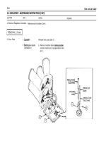
Cut two pieces of insulation sleeving 3/4 inches
long.
Slide insulation sleeving on wires.
Remove pins A and C.
Solder (item 9, app D) one pin to resistor wire
and one pin to ground wire. See TB SIG 222.
CAUTION
Be sure that pins are inserted into correct holes of electrical receptacle connector or discharger will
not fire.
i. Insert resistor wire pin into hole A.
j. Insert ground wire pin into hole C.
k. Slide insulation sleeving over soldered connec-
tions and heatshrink.
Back to Top


