TM-9-1040-267-20-P - Page 57 of 108
plate (2)
b. Screws (3)
a.
b.
INSTALLATION
CAUTION
To avoid damage to discharger, do not pinch wires between cover plate and discharger base.
Discharger Base
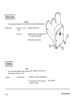
a. Gasket (1) and cover
Install gasket and cover plate.
Apply heavy coating of sealing compound (item
7 or 8, app D) to screw threads.
Install eight screws and tighten.
PAINTING
NOTE
Do not paint electrical receptacle connector, electrical contacts, nameplate, or screws. Do not let
paint clog mounting holes or drain holes.
Discharger
All outside surfaces
a.
b.
Remove burrs, corrosion, and chipped paint.
Touch up with primer (item 6, app D) and
See TM 43-0139.
enamel (item 3, app D).
2-43
TM 9-1040-267-20&P
Back to Top


