TM-9-1240-401-34-P - Page 70 of 590
TM 9-1240-401-34&P
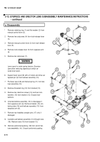
3-13. EYEPIECE AND ERECTOR LENS SUBASSEMBLY MAINTENANCE INSTRUCTIONS
- continued
b. Repair
1 Remove corrosion, grease, and dirt from all parts.
Refer to TM 9-254 for cleaning instructions.
2 Visually inspect for missing and damaged parts.
3 Repair or replace parts in accordance with author-
ized parts listed in appendix D.
c. Assembly
1 Position new gasket (44) and mount telescope
adapter (43) over wire leads on rear housing (31)
and secure with four new Iockwashers (42) and
four machine screws (41).
2
3
4
5
6
Install new gasket (40) over wire leads and position
receptacle connector (39) in front of leads. Slide
new insulation sleeving over wire leads and solder
leads to receptacle connector (39) using solder and
flux. Remove tags.
Secure receptacle connector (39) to mount tele-
scope adapter (43) with four new Iockwashers (38)
and four machine screws (37).
Position new gasket (36) on rear housing (31).
NOTE
Nut and Iockwasher are part of variable resis-
tor.
Assemble variable resistor (30) in variable resistor
housing (29) and secure with nut (34) and lock-
washer (35).
Position knob (33) on shaft of variable resistor (30)
and secure with setscrew (32).
NOTE
See para 3-26 for wiring diagram.
7
3-12
Slide insulation sleeving over wire leads and solder
wire leads to variable resistor (30) using solder and
flux. Remove tags.
Back to Top


