TM-9-1240-401-34-P - Page 72 of 590
TM 9-1240-401-34&P
3-13. EYEPIECE AND ERECTOR LENS SUBASSEMBLY MAINTENANCE
INSTRUCTIONS - continued
c. Assembly - continued
23
24
25
26
27
28
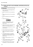
Apply a thin coat of grease (item 6, appx B) to the
round surface of manual control lever (3) and to the
tip of the manual control lever that engages the
lever spool (8).
Position lock-release lever (5) between flanges on
eyepiece arm (6) with lock-release lever (5) point-
ing toward eyeshield end of eyepiece arm (6).
Slide manual control lever (3) through flanges on
eyepiece arm (6) and lock-release lever (5). En-
sure that manual control lever (3) engages lock-re-
lease lever (5).
Secure manual control lever (3) to flanges of eye-
piece arm (6) with flat washer (2) and retaining ring
(1).
Apply sealing compound to setscrew holes and
install two setscrews (4).
Install warning labels (45 and 46) if removed.
3-14
Back to Top


