TM-9-1240-401-34-P - Page 85 of 590
TM 9-1240-401-34&P
3-19. LEVEL ASSEMBLY MAINTENANCE INSTRUCTIONS (Ml 18A2)
This task covers:
a. Removal b. Disassembly c. Repair
d. Assembly e. Installation
f. Adjustment
INITIAL SET-UP
Tools
Drill bit no. 44 (0.086) (Item 15, appx F)
Lockwashers (2) (Item 75, appx E)
Preformed packing (Item 39, appx E)
Drill bit no. 54 (0.055) (Item 16, appx F)
Sealing compound (Item 13, appx B)
Drill, electric 1/2" (Item 12, appx F)
Sealing compound (Item 15, appx B)
Shim (Item 49, appx E)
Tool Kit, Electronic System, Repair, Field Mainte-
Tape (Item 20, appx B)
nance(SC5180-95-CL-B29)
Tubular spanner wrench, 1-25/32 and 1-51/64
TM 9-254
inch (Item 32, appx F)
TM 750-116
Adhesive (Item 2, appx B)
M118A2 elbow telescope removed from howitzer
Lockwashers (4) (Item 68, appx E)
(TM 9-2350-311-10)
a. Removal
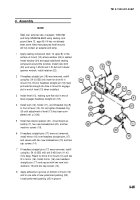
1 Remove four machine screws (1) and four lock-
washers (2). Discard Iockwashers.
2 Using tape, tag and disconnect two wires (3) by
removing machine screws (4 and 5).
3 Remove level assembly (6).
4 Remove two straight headless pins (7) only if dam-
aged.
3-27
Back to Top


