TM-9-1290-262-24-P - Page 72 of 192
ARMY TM 9-1290-262-24&P
MARINE CORPS TM 00476C-24&P
AIR FORCE TO 49A7-3-72/74
3-7. TEST AND ADJUSTMENT PROCEDURES (cont).
BACKLASH IN ORIENTING WORM (cont)
18
19
20
21
22
Install adapter (14) on orienting knob.
Install 0 to 80 in.-oz torque wrench (15) on
adapter and check for a running torque of
24.00 to 48.00 in.-oz (0.17 to 0.34 N-m).
Remove torque wrench and adapter.
If torque is out of tolerance, repeat steps 7
thru 20 and recheck torque.
Fill setscrew holes with sealing compound
(item 8, appx D).
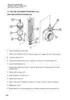
ELEVATION STOP MECHANISM
1
2
3
4
5
Bring elbow telescope reticle into coinci-
dence with test target (fig. E-6, appx E).
Set all scales, indexes, and micrometers to
zero.
Rotate elevation micrometer knob (1) to
elevate elbow telescope to limit of stop
rings. Elbow telescope must not touch
housing cover (2). Reading on aiming
circle elevation scale and micrometer must
beat least 1130 roils above horizontal.
Rotate elevation micrometer knob (1) to
depress elbow telescope to limit of stop
rings. Elbow telescope must not touch
housing cover (2). Reading on aiming
circle elevation scale and micrometer must
be at least 430 roils below horizontal.
If conditions of steps 3 and 4 above can-
not be met, proceed to steps 6 thru 17.
3-44
Back to Top


