TM-9-2320-260-20 - Page 1055 of 1337
TM 9-2320-260-20
I
13-34. WRECKER CONTROL VALVE HYDRAULIC HOSES REPLACEMENT
THIS TASK COVERS:
a. Removal
b. Installation
INITIAL SETUP
APPLICABLE MODELS
EQUIPMENT CONDITION
M816
.
Parking brake set (TM 9-2320-260-10).
MATERIALS/PARTS
.
Hydraulic oil reservoir drained (LO 9-2320-260-12).
• Restrictor valve removed (para. 13-32).
Two locknuts
REFERENCES (TM)
LO 9-2320-260-12
TM 9-2320-260-10
TM 9-2320-260-20P
NOT E
●
All hydraulic hoses are replaced basically the same. This
procedure covers the replacement of one hydraulic hose.
●
Tag and number all hose connectors with their corresponding
fitting before removing the part.
●
Have drainage container ready to catch oil.
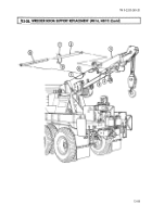
1. Remove two locknuts (6) and hose clamps (5) from gondola (2). Discard locknuts (6).
2. Remove hose (4) from extension lever connection (3).
3. Remove hose (4) from extension cylinder connection (1).
NOTE
Move tags from a damaged part to a replacement part before
discarding the damaged part.
4.
Remove hose (4) from gondola (2).
1.
Position hose (4) on gondola (2).
NOT E
Verify numbers marked on tags before installing hose connectors
on fittings.
2. Install hose (4) on extension cylinder connection (1).
3. Install hose (4) on extension lever connection (3).
4. Install hose (4) on gondola (2) with two clamps (5) and new locknuts (6).
13-82
Back to Top

