TM-9-2320-260-20 - Page 491 of 1337
TM 9-2320-260-20
I
4-26. LOW AIR PRESSURE INDICATOR SWITCH REPLACEMENT
w
THIS TASK COVERS:
a.
Removal
b. Installation
INITIAL SETUP
APPLICABLE MODELS
All
MATERIA1.S/PARTS
Two lockwashers
EQUIPMENT CONDITION
●
Parking brake set (TM 9-2320-260-10).
●
Air reservoirs drained (TM 9-2320-260-10).
GENERAL SAFETY INSTRUCTIONS
Antiseize tape (Appendix C, Item 30)
Do not disconnect air lines before draining air
REFERENCES fTM)
reservoirs.
TM 9-2320-260-10
TM 9-2320-260-20P
WARNING
Do not disconnect air lines before draining air reservoirs. Small
parts under pressure may shoot out with high velocity, causing
injury to personnel.
I
a. Removal
I
1.
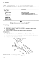
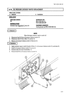
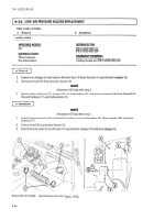
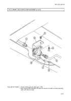
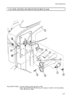
Disconnect leads (1) and (6) from switch (4).
2. Disconnect air line (7) from elbow (8).
●
3. Remove two screws (2), lockwashers (3), and switch (4) from firewall (5). Discard lockwashers (3).
4.
Remove elbow (8) from switch (4).
I
b. Installation
I
1. Apply anti seize tape to male threads of elbow (8).
2. Install elbow (8) on switch (4).
3. Install switch (4) on firewall (5) with two new lockwashers (3) and screws (2).
4. Connect air line (7) on elbow (8).
5. Connect leads (1) and (6) to switch (4).
4-50
Back to Top

