TM-9-2320-260-34-1 - Page 326 of 657
TM 9-2320-260-34-1
5-7. FUEL INJECTOR (NON-TOP STOP) MAINTENANCE
THIS TASK COVERS:
a. Disassembly
c. Assembly
b. Cleaning and Inspection
INITIAL SETUP
APPLICABLE MODELS
All
TOOLS
General mechanic’s tool kit
(Appendix B, Item 1)
Vise (Appendix B, Item 38)
Torque wrench, 1/2-in. dr.
(Appendix B, Item 3)
Loading fixture
Cup retainer wrench (Appendix B, Item 21)
Injector body wrench (Appendix B, Item 23)
MATERIALS/PARTS
Injector overhaul repair kit
(Appendix D, Item 336)
MATERIALS/PARTS (Contd)
Drycleaning solvent (Appendix C, Item 48)
Cleaning cloth (Appendix C, Item 9)
Diesel fuel (Appendix C, Item 13)
REFERENCES (TM)
TM 9-2320-260-10
TM 9-2320-260-34P-1
EQUIPMENT CONDITION
l Parking brake set (TM 9-2320-260-10).
l Fuel injectors removed (para. 5-6).
GENERAL SAFETY INSTRUCTIONS
Keep fire extinguisher nearby when using
drycleaning solvent.
a. Disassembly
WARNING
Drycleaning solvent is flammable and will not be used near open
flame. Use only in well-ventilated places. Failure to do this may
result in injury to personnel.
CAUTION
Improper cleaning methods and use of unauthorized cleaning
solvents can damage equipment.
1. Clean exterior of injector (1) with drycleaning solvent.
CAUTION
Injector barrel and plunger are a matched pair (class fit). Do
not interchange. Do not touch internal parts unless hands are
moistened with diesel fuel. Failure to do this may result in
damage to equipment.
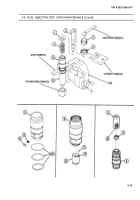
2. Remove plunger (2) and spring (3) from injector (1).
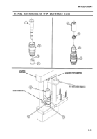
3. Install injector body wrench in vise.
4. Install injector (1) into body wrench so flat machined areas on injector (1) are secure in body wrench.
5. Using cup retainer wrench, loosen cup retainer (4).
6. Remove injector (1) from body wrench.
NOTE
Position injector so cup retainer is in an upward position. This will
prevent cup, barrel, and check ball from falling out of injector.
7. Remove cup retainer (4) from adapter (7).
8. Remove injector cup (5) from barrel (6). Discard injector cup (5).
5-6
Back to Top

