TM-9-2320-260-34-2 - Page 143 of 863
15-27. RETRACTABLE BEAM ROLLERS REPLACEMENT
THIS TASK COVERS:
a. Support Roller Removal
c. End Roller Removal
b. Support Roller Installation
d. End Roller Installation
lNITIAL SETUP
APPLICABLE MODELS
M820, M820A1, M820A2
TOOLS
General mechanic’s tool kit
(Appendix B, Item 1)
MATERIALS/PARTS
Two cotter pins (support roller)
(Appendix D, Item 20)
Two cotter pins (end roller)
(Appendix D, Item 21)
REFERENCES (TM)
TM 9-2320-260-10
TM 9-2320-260-34P-2
EQUIPMENT CONDITION
●
Parking brake set (TM 9-2320-260-10).
●
Van body sides fully expanded and secured
(TM 9-2320-260-10).
SPECIAL ENVIRONMENTAL CONDITIONS
Vehicle must be on level surface.
NOTE
All ten support rollers and end rollers are replaced the same. This
procedure covers the left-rear support and end roller.
a. Support Roller Removal
NOTE
The left-rear cover is secured with seven screws. All other covers
are secured with eight screws.
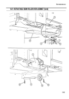
1. Remove seven screws (3), two clamps (2), and cover (4) from underframe (1).
2. Remove two cotter pins (5) from support roller shaft (7). Discard cotter pins (5).
3. Remove support roller shaft (7) and support roller (6) from underframe (1).
b. Support Roller Installation
1. Install support roller (6) on underframe (1) with support roller shaft (7).
2. Install two new cotter pins (5) in support roller shaft (7).
NOTE
The Ieft-rear cover is secured with seven screws. All other covers
are secured with eight screws.
--
3. Install cover (4) and two clamps (2) on underframe (1) with seven screws (3).
15-82
TM 9-2320-260-34-2
Back to Top


