TM-9-2320-260-34-2 - Page 555 of 863
16-26. CRANE TURNTABLE MAINTENANCE (M816)
THIS TASK
COVERS:
a. Removal
d. Assembly
b. Disassembly
e. Installation
c. Cleaning and Inspection
APPLICABLE MODELS
EQUIPMENT CONDITION
M816
TOOLS
General mechanic’s tool kit
(Appendix B, Item 1)
Lifting device
Eight washers (Appendix C, Item 56)
Four nuts (Appendix C, Item 24)
Four screws (Appendix C, Item 33)
MATERIALS/PARTS
Two lockwashers (Appendix D. Item 213)
•
•
•
•
Floodlight wiring harness removed
(TM 9-2320-260-20).
Hoist bevel gearcase removed (para. 16-25).
Hydraulic pump and support removed
(para. 16-24).
Crane gearcase removed (para. 16-28).
Crane boom elevating cylinders removed
(para. 16-14).
Crane gondola assembly removed (para. 16-22).
Hydraulic oil reservoir removed
(TM 9-2320-260-20).
Boom assembly removed (para. 16-18).
Eighteen locknuts (Appendix D, Item 173)
GENERAL SAFETY lNSTRUCTlONS
Eight lockwashers (Appendix D, Item 223)
GAA grease (Appendix C, Item 14)
• All personnel must stand clear during lifting
AntiSeize
tape (Appendix C, Item 50)
operations.
•
Ensure lifting capacity is greater than weight of
REFERENCES (TM)
boom support.
TM 9-237
LO 9-2320-260-12
TM 9-2320-260-20
TM 9-2320-260-34P-2
NOTE
Assistant will help with step 1.
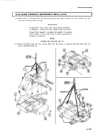
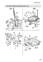
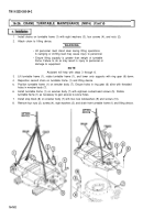
1. Attach chains and lifting device to boom support (1). Take up slack in chains.
2. Remove eighteen screws (2) and locknuts (3) from boom support (1) and turntable frame (6). Discard
locknuts (3).
WARNIN G
• All personnel must stand clear during Iifting operations.
A swinging or shifting load may cause injury to personnel.
• Ensure lifting capacity is greater than weight (30 lb (14 kg)) of
boom support. Failure to do so may result m injury to personnel
or damage to equipment.
NOTE
Assistant will help with step 3.
3. Remove boom support (1) from turntable frame (6).
4. Remove four screws (4) and right-hand guard (5) from turntable frame (6).
5. Remove four screws (7) an left-hand guard (8) from turntable frame (6).
6. Rotate turntable frame (6) 90° clockwise and remove two screws (14), lockwashers (13), and stop
block (12) from wrecker body (11). Discard lockwashers (13).
7. Remove socket-head screw (9) from ring•gear (10).
8. Rotate turntable frame (6) and remove next socket head screw (9) from ring gear (10). Repeat until
all eighteen socket-head screws (9) are removed.
16-156
TM 9-2320-260-34-2
•
•
•
•
Back to Top


