TM-9-2320-272-23-2 - Page 1069 of 1417
REMOVAL
NOTE
Assistant will help with Step (1).
1.
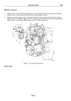
Remove screw (Figure 2, Item 1), lockwasher (Figure 2, Item 2), two screws (Figure 2, Item 16), washers
(Figure 2, Item 17), screws (Figure 2, Item 15), lockwashers (Figure 2, Item 14), and washers
(Figure 2, Item 13) from fan pulley bracket (Figure 2, Item 3). Discard lockwashers.
2.
Lower fan pulley bracket (Figure 2, Item 3).
3.
Loosen six screws (Figure 2, Item 6) holding support bracket (Figure 2, Item 4) to engine.
4.
Place brass drift punch (Figure 2, Item 11) against stud (Figure 2, Item 9) on water pump housing
(Figure
2,
Item
10) and turn stud counterclockwise to release drivebelt (Figure 2, Item 8) tension.
5.
Remove drivebelt (Figure 2, Item 8) from pump pulley (Figure 2, Item 7) and accessory drive pulley
(Figure 2, Item 5).
TM 9-2320-272-23-2
0294
0294-4
Back to Top


