TM-9-2320-272-23-2 - Page 529 of 1417
REMOVAL
NOTE
Assistant will help with this procedure.
1.
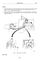
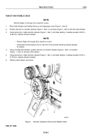
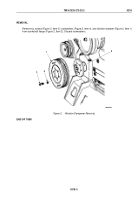
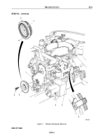
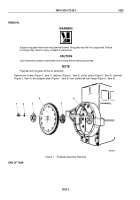
Remove plug (Figure 1, Item 4) and preformed packing (Figure 1, Item 3) from flywheel housing (Figure 1,
Item 2). Discard
preformed packing.
2.
Using engine barring tool (Figure 1, Item 9), prevent crankshaft (Figure 1, Item 1) from turning.
3.
Remove four screws (Figure 1, Item 6) and vibration damper (Figure 1, Item 5) from crankshaft
(Figure
1,
Item
1).
4.
Inspect vibration damper (Figure 1, Item 5) for bends, breaks, and damaged pulley grooves. Replace vibration
damper (Figure 1, Item 5) if bent, broken, or grooves are damaged.
5.
Inspect vibration damper alignment marks (Figure 1, Item 8). Replace vibration damper (Figure 1, Item 5) if
alignment marks are 0.063 in. (1.60 mm) out of alignment.
6.
Inspect rubber member (Figure 1, Item 7) for wear and damage. Replace vibration damper (Figure 1, Item 5)
if damaged or worn more than 0.125 in. (3.18 mm) deeper than face of vibration damper.
TM 9-2320-272-23-2
0219
0219-2
Back to Top

