TM-9-2320-272-23-2 - Page 607 of 1417
INSTALLATION
1.
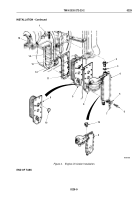
Install bracket (Figure 2, Item 11) on oil suction tube (Figure 2, Item 13) with screw (Figure 2, Item 16), washer
(Figure 2, Item 17), and locknut (Figure 2, Item 18).
2.
Install gasket (Figure 2, Item 10) and oil suction tube (Figure 2, Item 13) on engine block (Figure 2, Item 1)
with two spacers (Figure 2, Item 15) and screws (Figure 2, Item 14).
3.
Install bracket (Figure 2, Item 11) on engine block (Figure 2, Item 1) with two screws (Figure 2, Item 12).
NOTE
Prior to installation, fill joint between oil pan rail, front gear case cover, and rear cover with
sealing compound.
4.
Apply sealing compound to mating surfaces of engine block (Figure 2, Item 1) and oil pan (Figure 2, Item 6).
5.
Position gasket (Figure 2, Item 2) on oil pan (Figure 2, Item 6) with raised bead facing oil pan.
6.
Install oil pan (Figure 2, Item 6) on engine block (Figure 2, Item 1) with 32 lockwashers (Figure 2, Item 3),
washers (Figure 2, Item 4), and screws (Figure 2, Item 5).
7.
Install flat washer (Figure 2, Item 7), washer (Figure 2, Item 9), and two plugs (Figure 2, Item 8) on oil pan
(Figure
2,
Item
6).
TM 9-2320-272-23-2
0230
0230-4
Back to Top


