TM-9-2320-272-23-2 - Page 731 of 1417
INSTALLATION
NOTE
Floor mat must be pulled back to gain access to one screw hole in Steps (1) and (2).
1.
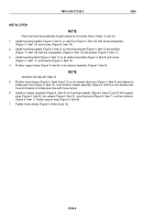
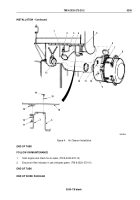
Install mounting bracket (Figure 4, Item 5) on cab floor (Figure 4, Item 16) with three lockwashers
(Figure
4,
Item
15) and screws (Figure 4, Item 14).
2.
Install mounting bracket (Figure 4, Item 3) on mounting bracket (Figure 4, Item 5) and subfloor
(Figure
4,
Item
18) with two lockwashers (Figure 4, Item 15) and screws (Figure 4, Item 17).
3.
Install mounting band (Figure 4, Item 7) on air cleaner assembly (Figure 4, Item 9) with screw
(Figure
4,
Item
11) and locknut (Figure 4, Item 10).
4.
Position support strap (Figure 4, Item 8) on air cleaner assembly (Figure 4, Item 9).
NOTE
Assistant will help with Step (5).
5.
Position hose clamps (Figure 4, Items 6 and 12) on air cleaner tube hose (Figure 4, Item 4) and cleaner-to-
intake pipe hose (Figure 4, Item 13), and install air cleaner assembly (Figure 4, Item 9) on air cleaner tube
hose and cleaner-to-intake pipe hose with hose clamps.
6.
Install air cleaner assembly (Figure 4, Item 9) on mounting brackets (Figure 4, Items 3 and 5) with support
strap (Figure 4, Item 8), two screws (Figure 4, Item 2), mounting band (Figure 4, Item 7), and two locknuts
(Figure 4, Item 1). Fasten support strap (Figure 4, Item 8).
7.
Tighten hose clamps (Figure 4, Items 6 and 12).
TM 9-2320-272-23-2
0245
0245-6
Back to Top


