TM-9-2320-272-23-3 - Page 117 of 1469
REMOVAL - Continued
47.
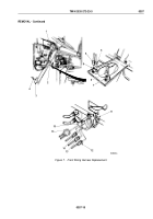
Disconnect wires (Figure 8, Items 2 and 3) from ether start switch (Figure 8, Item 1).
48.
Disconnect wires (Figure 8, Items 5, 6, and 7) from heater blower motor switch (Figure 8, Item 4).
49.
Disconnect wire (Figure 8, Item 9) from warning signal lamp switch (Figure 8, Item 8).
NOTE
After harness wires have been removed in Steps (50) through (52), cables and hardware
should be installed on terminal adapters for installation.
50.
Remove nut (Figure 8, Item 10), screw (Figure 8, Item 14), battery cables (Figure 8, Items 11 and 12), and
wire (Figure 8, Item 13) from terminal adapter (Figure 8, Item 15).
51.
Remove nut (Figure 8, Item 16), screw (Figure 8, Item 19), wire (Figure 8, Item 20), and battery cable
(Figure
8,
Item
18) from terminal adapter (Figure 8, Item 17).
52.
Remove nut (Figure 8, Item 21), screw (Figure 8, Item 23), battery cables (Figure 8, Items 22 and 26), and
wire (Figure 8, Item 24) from terminal adapter (Figure 8, Item 25).
53.
Push wires (Figure 8, Items 13, 20, and 24) through hole in cab floor.
54.
Remove four screws (Figure 8, Item 36) from warning light panel (Figure 8, Item 28) and pull panel away from
instrument panel (Figure 8, Item 29).
55.
Disconnect wire (Figure 8, Item 30) from parking brake indicator light (Figure 8, Item 27).
56.
Disconnect wire (Figure 8, Item 31) from low air pressure indicator light (Figure 8, Item 41).
57.
Disconnect wire (Figure 8, Item 32) from spring brake override indicator light (Figure 8, Item 40).
58.
Disconnect wire (Figure 8, Item 33) from engine hot indicator light (Figure 8, Item 39).
59.
Disconnect wire (Figure 8, Item 34) from axle lock-in indicator light (Figure 8, Item 38).
60.
Disconnect wire (Figure 8, Item 35) from high-beam indicator light (Figure 8, Item 37).
TM 9-2320-272-23-3
0357
0357-16
Back to Top


