TM-9-2320-272-23-3 - Page 121 of 1469
REMOVAL - Continued
77.
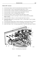
Place transmission selector assembly (Figure 10, Item 1) in N (neutral) position.
78.
Remove four screws (Figure 10, Item 3), lockwashers (Figure 10, Item 4), and transmission selector assembly
(Figure 10, Item 1) from console (Figure 10, Item 2). Discard lockwashers.
79.
Disconnect transmission selector wires (Figure 10, Items 5, 6, and 7) from three harness leads
(Figure
10,
Item
8).
NOTE
Perform Step (80) for M936 wrecker only.
80.
Disconnect connector (Figure 10, Item 9) from connector (Figure 10, Item 10) of floodlight switch
(Figure
10,
Item
25) and auxiliary receptacle (Figure 10, Item 26).
81.
Remove cap (Figure 10, Item 17) from connector (Figure 10, Item 22).
82.
Remove nut (Figure 10, Item 13), lockwasher (Figure 10, Item 14), screw (Figure 10, Item 19), and ground
wire (Figure 10, Item 15) from mounting bracket (Figure 10, Item 21). Discard lockwasher.
83.
Remove nut (Figure 10, Item 11), lockwasher (Figure 10, Item 12), screw (Figure 10, Item 18), and cap chain
(Figure 10, Item 16) from mounting bracket (Figure 10, Item 21). Discard lockwasher.
84.
Remove two nuts (Figure 10, Item 24), lockwashers (Figure 10, Item 23), screws (Figure 10, Item 20), and
connector (Figure 10, Item 22) from three mounting brackets (Figure 10, Item 21). Discard lockwashers.
TM 9-2320-272-23-3
0357
0357-20
Back to Top


