TM-9-2320-272-23-3 - Page 127 of 1469
INSTALLATION - Continued
5.
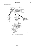
Install connector (Figure 13, Item 17) on top of mounting bracket (Figure 13, Item 13) under right side of
instrument panel (Figure 13, Item 14) with two screws (Figure 13, Item 12), lockwashers
(Figure
13,
Item
18), and nuts (Figure 13, Item 19).
6.
Install cap chain (Figure 13, Item 8) on mounting bracket (Figure 13, Item 13) with screw
(Figure
13,
Item
10), lockwasher (Figure 13, Item 4), and nut (Figure 13, Item 3).
7.
Install ground wire (Figure 13, Item 7) on mounting bracket (Figure 13, Item 13) with screw
(Figure
13,
Item
11), lockwasher (Figure 13, Item 6), and nut (Figure 13, Item 5).
8.
Install cap (Figure 13, Item 9) on connector (Figure 13, Item 17).
9.
Connect connector (Figure 13, Item 2) to connector (Figure 13, Item 1) of floodlight switch
(Figure
13,
Item
15) and auxiliary receptacle (Figure 13, Item 16).
10.
Place wires (Figure 13, Items 24, 25, and 26) in console (Figure 13, Item 21) and connect to selector assembly
wires (Figure 13, Items 22, 23, and 29).
11.
Install transmission selector assembly (Figure 13, Item 20) on console (Figure 13, Item 21) with four
lockwashers (Figure 13, Item 28) and screws (Figure 13, Item 27).
TM 9-2320-272-23-3
0357
0357-26
Back to Top


