TM-9-2320-272-23-3 - Page 483 of 1469
REMOVAL
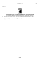
WARNING
Air system components are subject to high pressure. Always relieve pressure before
loosening or removing air system components. Failure to comply may result in injury or death
to personnel.
1.
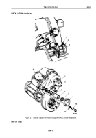
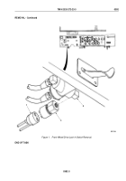
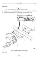
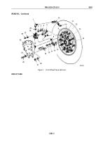
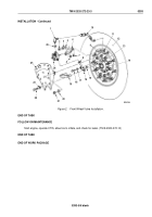
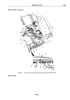
Remove cap (Figure 1, Item 26) and valve stem (Figure 1, Item 27) from tank valve (Figure 1, Item 28), and
allow tire (Figure 1, Item 12) to deflate completely. Install valve stem (Figure 1, Item 27) and cap
(Figure
1,
Item 26) on tank valve (Figure 1, Item 28).
2.
Remove two locknuts (Figure 1, Item 21), washers (Figure 1, Item 20), screws (Figure 1, Item 22), washers
(Figure 1, Item 23), shield (Figure 1, Item 25), and spacer (Figure 1, Item 19) from studs (Figure 1, Item 9) and
axle flange (Figure 1, Item 14). Discard locknuts.
3.
Remove hose (Figure 1, Item 10) from elbow (Figure 1, Item 1) and turret valve (Figure 1, Item 11).
4.
Loosen nut (Figure 1, Item 8) and remove air manifold (Figure 1, Item 16) from wheel valve
(Figure
1,
Item
24).
5.
Remove screw (Figure 1, Item 18), washer (Figure 1, Item 17), air manifold (Figure 1, Item 16), and o-ring
(Figure 1, Item 15) from axle flange (Figure 1, Item 14) and air tube (Figure 1, Item 13). Discard o-ring.
6.
Remove two locknuts (Figure 1, Item 2), washers (Figure 1, Item 3), washers (Figure 1, Item 5), and wheel
valve (Figure 1, Item 24) from studs (Figure 1, Item 9). Discard locknuts.
7.
Remove three locknuts (Figure 1, Item 7), lockwashers (Figure 1, Item 4), and bracket (Figure 1, Item 6) from
wheel valve (Figure 1, Item 24). Discard locknuts and lockwashers.
8.
Remove elbow (Figure 1, Item 1) and o-ring (Figure 1, Item 29) from wheel valve (Figure 1, Item 24).
Discard
o-ring.
NOTE
For repair of wheel valves, refer to (WP
0482).
9.
For General Cleaning Instructions, refer to (Volume 5, WP
0819).
10.
For General Inspection Instructions, refer to (Volume 5, WP
0819).
11.
Inspect wheel valve (Figure 1, Item 24) for cracks, leaks, and stripped threads. Replace or repair wheel valve
(Figure 1, Item 24) if cracked, leaking, or threads are stripped.
12.
Inspect bracket (Figure 1, Item 6), shield (Figure 1, Item 25), air manifold (Figure 1, Item 16), hose
(Figure
1,
Item 10), spacer (Figure 1, Item 19), elbow (Figure 1, Item 1), and turret valve (Figure 1, Item 11)
for cracks, bends, or stripped threads. Replace parts if damaged.
TM 9-2320-272-23-3
0393
0393-2
Back to Top

