TM-9-2320-272-23-3 - Page 485 of 1469
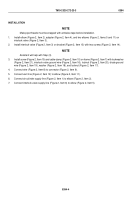
INSTALLATION
NOTE
Wrap all male pipe threads with antiseize tape before installation.
1.
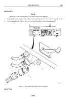
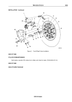
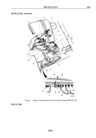
Install hose (Figure 2, Item 10) on turret valve (Figure 2, Item 11).
2.
Install o-ring (Figure 2, Item 15) on air tube (Figure 2, Item 13).
3.
Install o-ring (Figure 2, Item 26) and elbow (Figure 2, Item 1) on wheel valve (Figure 2, Item 24). Finger tighten
elbow (Figure 2, Item 1).
4.
Install bracket (Figure 2, Item 6) on wheel valve (Figure 2, Item 24) with three lockwashers
(Figure
2,
Item
4) and locknuts (Figure 2, Item 7).
NOTE
Ensure air manifold is properly seated on wheel before tightening.
5.
Connect air manifold (Figure 2, Item 16) on wheel valve (Figure 2, Item 24). Finger-tighten nut
(Figure
2,
Item
8), but allow for movement.
6.
Install wheel valve (Figure 2, Item 24) with bracket (Figure 2, Item 6) on two studs (Figure 2, Item 9) with
washers (Figure 2, Item 5), washers (Figure 2, Item 3), and locknuts (Figure 2, Item 2). Finger-tighten locknuts.
7.
Install screw (Figure 2, Item 18) and washer (Figure 2, Item 17) on air manifold (Figure 2, Item 16) and axle
flange (Figure 2, Item 14). Finger-tighten screw.
8.
Tighten two locknuts (Figure 2, Item 2), screw (Figure 2, Item 18), and nut (Figure 2, Item 8).
9.
Tighten elbow (Figure 2, Item 1) to align with hose (Figure 2, Item 10) and connect hose (Figure 2, Item 10)
to elbow.
NOTE
Spacer has long and short end. Install short end of spacer on flange of air manifold.
10.
Install spacer (Figure 2, Item 19) and shield (Figure 2, Item 25) on axle flange (Figure 2, Item 14) with two
washers (Figure 2, Item 23) and screws (Figure 2, Item 22).
11.
Install two washers (Figure 2, Item 20) and locknuts (Figure 2, Item 21) on studs (Figure 2, Item 9).
TM 9-2320-272-23-3
0393
0393-4
Back to Top

