TM-9-2320-272-23-3 - Page 565 of 1469
INSTALLATION - Continued
NOTE
•
Perform Steps (7) through (10) for right side of vehicle.
•
Soak felt pad in lubricating oil before installation.
7.
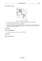
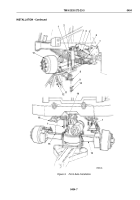
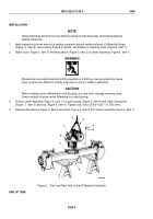
Install clip (Figure 4, Item 4) and felt pad (Figure 4, Item 5) on steering knuckle ball (Figure 4, Item 6).
8.
Install steering assist cylinder (Figure 4, Item 3) on steering knuckle ball (Figure 4, Item 6). Tighten adjustable
plug (Figure 4, Item 7), then back off until slots align with holes (Figure 4, Item 1).
9.
Install cotter pin (Figure 4, Item 2) on steering assist cylinder (Figure 4, Item 1).
10.
Bend tabs of clip (Figure 4, Item 4) over felt pad (Figure 4, Item 5) and steering knuckle ball (Figure 4, Item 6).
NOTE
Perform Steps (11) and (12) for left side of vehicle.
11.
Install drag link (Figure 4, Item 16) on steering knuckle arm (Figure 4, Item 15) with nut (Figure 4, Item 13).
Tighten nut (Figure 4, Item 13) 140 to 180 lb-ft (190 to 244 N·m).
12.
Install cotter pin (Figure 4, Item 14) in nut (Figure 4, Item 13) and drag link (Figure 4, Item 16).
NOTE
•
Wrap all male pipe threads with antiseize tape before installation.
•
Perform Step (13) for M939A2 series vehicles.
13.
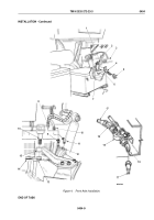
Connect two air lines (Figure 4, Item 17) to adapters (Figure 4, Item 18) on relief safety valve
(Figure
4,
Item
19).
14.
Install elbow (Figure 4, Item 11) and adapter (Figure 4, Item 9) on left and right service brake chambers
(Figure
4,
Item
12).
15.
Connect two primary lines (Figure 4, Item 8) and vent lines (Figure 4, Item 10) to elbows (Figure 4, Item 11)
and adapters (Figure 4, Item 9).
TM 9-2320-272-23-3
0404
0404-8
Back to Top

