TM-9-2320-272-23-3 - Page 597 of 1469
INSTALLATION
1.
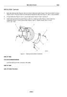
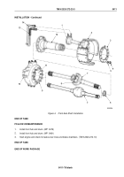
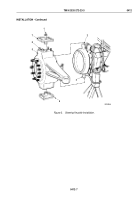
Install washer (Figure 4, Item 6) on axle shaft (Figure 4, Item 7).
2.
Lubricate universal joint (Figure 4, Item 8) (if equipped), grease all bearing surfaces on axle shaft
(Figure
4,
Item
7), and fill steering knuckle cavity (Figure 4, Item 11) with GAA grease.
3.
Support axle shaft (Figure 4, Item 7) and install in steering knuckle housing (Figure 4, Item 10).
4.
Repack steering knuckle cavity (Figure 4, Item 11) with GAA grease.
5.
Apply sealing compound to spindle (Figure 4, Item 12) and align with mounting studs (Figure 4, Item 9) on
steering knuckle housing (Figure 4, Item 10). Ensure spindle is slot end up.
6.
Install brake shoe spider and chamber assembly (Figure 4, Item 2) over spindle (Figure 4, Item 12) on steering
knuckle housing (Figure 4, Item 10).
7.
Install brake spider (Figure 4, Item 3) on steering knuckle housing (Figure 4, Item 10) with ten washers
(Figure
4,
Item
5) and nuts (Figure 4, Item 4).
NOTE
Male pipe threads must be wrapped with antiseize tape before installation.
8.
Connect vent air line (Figure 4, Item 14) and service brake air line (Figure 4, Item 13) to front brake chamber
(Figure 4, Item 1).
TM 9-2320-272-23-3
0411
0411-6
Back to Top

