TM-9-2320-272-23-3 - Page 603 of 1469
CLEANING AND INSPECTION
1.
For General Cleaning Instructions, refer to (Volume 5, WP
0819).
2.
For General Cleaning Instructions, refer to (Volume 5, WP
0819).
3.
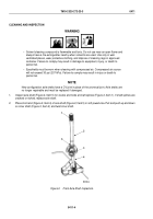
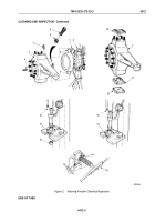
Inspect steering knuckle (Figure 2, Item 7), lower plate (Figure 2, Item 12), upper sleeve (Figure 2, Item 10),
and lower sleeve (Figure 2, Item 11) for cracks and scores. Replace part(s) if cracked or scored.
4.
Measure bearing inside diameter of upper and lower sleeves (Figure 2, Items 10 and 11) for wear. If inside
diameter is more than 1.505 in. (38.23 mm), replace sleeve.
5.
Inspect studs (Figure 2, Items 1 and 6) for stripped threads. Replace studs if threads are stripped.
6.
Inspect machine bolt (Figure 2, Item 8) for bends. Replace machine bolt if bent.
NOTE
•
Perform Steps (7) and (8) if replacing machine bolt.
•
Perform Steps (9) through (11) if replacing sleeve bearings. Steps to replace sleeve
bearings are the same for upper and lower sleeves.
7.
Break weld and remove stop screw (Figure 2, Item 8) and jamnut (Figure 2, Item 9) from steering knuckle
(Figure 2, Item 7). Discard machine bolt and plain hexagon nut.
8.
Install machine bolt (Figure 2, Item 8) and plain hexagon nut (Figure 2, Item 9) on steering knuckle
(Figure
2,
Item
7). Do not weld.
9.
Using arbor press (Figure 2, Item 15), remove sleeve bearing (Figure 2, Item 14) from sleeve
(Figure
2,
Item
13). Discard sleeve bearing.
10.
Using arbor press (Figure 2, Item 15), install sleeve bearing (Figure 2, Item 14) in sleeve (Figure 2, Item 13).
11.
Using burnisher (Figure 2, Item 16), burnish inside diameter of sleeve bearing (Figure 2, Item 14) to 1.500 in.
(38.1 mm).
TM 9-2320-272-23-3
0412
0412-4
Back to Top

