TM-9-2320-272-23-3 - Page 607 of 1469
INSTALLATION - Continued
6.
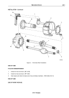
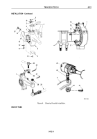
Install steering knuckle arm (Figure 4, Item 7) on studs (Figure 4, Item 2) with four bushings
(Figure
4,
Item
8), lockwashers (Figure 4, Item 4), and nuts (Figure 4, Item 5). Tighten nuts 155 to 170 lb-ft
(210 to 231 N·m).
7.
Install grease fitting (Figure 4, Item 6) on steering knuckle arm (Figure 4, Item 7).
8.
Install seal (Figure 4, Item 16) and dust seal plate (Figure 4, Item 19) on steering knuckle (Figure 4, Item 1)
with twelve screws (Figure 4, Item 18) and lockwire (Figure 4, Item 17).
NOTE
Lower sleeve must be installed with words WHEEL END facing down.
9.
Apply sealing compound to contact surface of lower plate (Figure 4, Item 8), and install lower plate
(Figure
4,
Item
9) and seal guard (Figure 4, Item 13) on steering knuckle (Figure 4, Item 1) with lockwashers
(Figure
4,
Item
12) and screws (Figure 4, Item 11). Ensure seal guard (Figure 4, Item 13) is installed in front
two mounting holes. Tighten screws 105 to 135 lb-ft (142 to 183 N·m)
10.
Install grease fitting (Figure 4, Item 10) on lower plate (Figure 4, Item 8).
11.
Install two washers (Figure 4, Item 14) and screws (Figure 4, Item 15) on seal guard (Figure 4, Item 13) and
steering knuckle (Figure 4, Item 1). Tighten screws 105 to 135 lb-ft (142 to 183 N·m).
12.
Install tie rod (Figure 4, Item 29) on steering knuckle (Figure 4, Item 1) with nut (Figure 4, Item 28). Tighten
nut 140 to 180 lb-ft (190 to 244 N·m).
13.
Install cotter pin (Figure 4, Item 27) on nut (Figure 4, Item 28) and tie rod (Figure 4, Item 29).
NOTE
•
Perform Step (14) for left steering knuckle.
•
Assistant will help with Step (14).
14.
Install drag link (Figure 4, Item 24) on steering knuckle arm (Figure 4, Item 7) with nut (Figure 4, Item 26).
Tighten nut 140 to 180 lb-ft (190 to 244 N·m).
15.
Install cotter pin (Figure 4, Item 25) on nut (Figure 4, Item 26) and drag link (Figure 4, Item 24).
NOTE
Perform Step (16) for right steering knuckle arm.
16.
Install socket assembly (Figure 4, Item 20) with ball stud (Figure 4, Item 23) on steering knuckle arm
(Figure
4,
Item
7) with nut (Figure 4, Item 22). Tighten nut 140 to 180 lb-ft (190
to
244
N·m).
17.
Install cotter pin (Figure 4, Item 21) on nut (Figure 4, Item 22) and socket assembly (Figure 4, Item 20).
TM 9-2320-272-23-3
0412
0412-8
Back to Top

