TM-9-2320-272-23-3 - Page 615 of 1469
REMOVAL
WARNING
Weight of vehicle must remain supported on jack stands at all times. Do not attempt to support
weight of vehicle on hydraulic jack. Failure to comply may result in injury or death to personnel.
NOTE
Forward-rear and rear-rear axles are replaced the same way. This procedure covers
replacement of the rear-rear axle.
1.
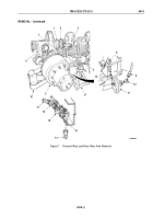
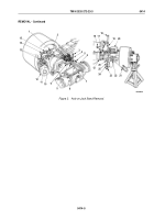
Position hydraulic jack (Figure 1, Item 16) under differential housing (Figure 1, Item 6) and raise vehicle.
2.
Position jack stands (Figure 1, Item 17) under spring seats (Figure 1, Item 4) and rear axle (Figure 1, Item 5)
and lower vehicle until spring seats and rear axle rest on jack stands.
3.
Remove eight locknuts (Figure 1, Item 7), screws (Figure 1, Item 3), and propeller shaft (Figure 1, Item 2) from
companion flange (Figure 1, Item 1). Discard locknuts.
WARNING
Do not disconnect air lines or hoses before draining air reservoirs. Small parts under pressure
may shoot out with high velocity. Failure to comply may result in injury or death to personnel.
NOTE
•
Perform Step (4) for M939A2 series vehicles only.
•
Tag all air lines for installation.
4.
Disconnect two air lines (Figure 1, Item 13) from elbows (Figure 1, Item 14) on relief valve (Figure 1, Item 15).
5.
Disconnect primary line (Figure 1, Item 9) and vent line (Figure 1, Item 8) and remove elbows
(Figure
1,
Items
10
and
12) from right and left service brake chambers (Figure 1, Item 11).
TM 9-2320-272-23-3
0414
0414-2
Back to Top

