TM-9-2320-272-23-3 - Page 623 of 1469
INSTALLATION - Continued
6.
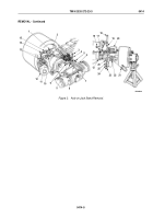
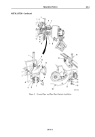
Install brake chamber bracket (Figure 5, Item 10) on left and right upper spring brackets (Figure 5, Item 5) with
washer (Figure 5, Item 4), screw (Figure 5, Item 3), washer (Figure 5, Item 4), lockwasher (Figure
5,
Item
8),
and nut (Figure 5, Item 9). Finger-tighten nuts.
7.
Position two upper torque rod brackets (Figure 5, Item 12) over dowel pins (Figure 5, Item 17) on rear axle
(Figure 5, Item 18) and install on upper torque rod plates (Figure 5, Item 14) with four screws
(Figure
5,
Item
13), lockwashers (Figure 5, Item 15), and nuts (Figure 5, Item 16).
8.
Install U-bolt bracket (Figure 5, Item 7) and U-bolt (Figure 5, Item 6) on left and right service brake chamber
brackets (Figure 5, Item 10) with two washers (Figure 5, Item 2) and nuts (Figure 5, Item 1).
NOTE
Assistant will help with Step (9).
9.
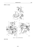
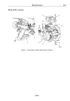
Install brake chamber bracket (Figure 5, Item 10) on left and right upper spring brackets (Figure 5, Item 5) with
washer (Figure 3, Item 4), screw (Figure 5, Item 3), washer (Figure 5, Item 4), lockwasher (Figure 5, Item 9),
and nut (Figure 5, Item 8). Tighten nuts (Figure 4, Item 5) and (Figure 5, Item 8) 350 to 375 lb-ft
(475 to 509 N·m).
10.
Install U-bolt bracket (Figure 5, Item 7) and U-bolt (Figure 5, Item 6) on left and right spring brakes
(Figure
5,
Item
11) with two washers (Figure 5, Item 2) and nuts (Figure 5, Item 1).
TM 9-2320-272-23-3
0414
0414-10
Back to Top

