TM-9-2320-272-23-3 - Page 626 of 1469
INSTALLATION - Continued
NOTE
Perform Step (14) for M939A2 series vehicles.
14.
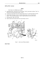
Install elbows (Figure 7, Items 8 and 10), vent line (Figure 7, Item 6), and primary line (Figure 7, Item 7) on
right and left service brake chambers (Figure 7, Item 9).
15.
Connect two air lines (Figure 6, Item 16) to elbows (Figure 6, Item 17) on relief valve (Figure 6, Item 18).
16.
Install propeller shaft (Figure 7, Item 2) on companion flange (Figure 7, Item 1) with eight screws
(Figure
7,
Item
3) and locknuts (Figure 7, Item 4). Tighten locknuts 32 to 40 lb-ft (43 to 54 N·m).
17.
Install wheels (WP
0484) or (WP
0485).
18.
Remove hydraulic jack and jack stands from rear axle (Figure 7, Item 5).
M7092-1DAA
4
6
7
8
9
10
5
3
2
1
Figure 7.
Axle Lines and Fittings Installation.
END OF TASK
TM 9-2320-272-23-3
0414
0414-13
Back to Top

