TM-9-2320-272-23-3 - Page 617 of 1469
REMOVAL - Continued
6.
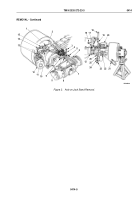
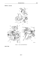
Disconnect vent lines (Figure 2, Items 1 and 2), secondary line (Figure 2, Item 11), and spring brake override
line (Figure 2, Item 10) and remove two adapter elbows (Figure 2, Item 13), elbow (Figure 2, Item 14), and tee
fitting (Figure 2, Item 15) from brake chamber bracket (Figure 2, Item 26).
7.
Remove primary line (Figure 2, Item 6), secondary line (Figure 2, Item 8), and two adapter fittings
(Figure
2,
Item
5) from mounting plate (Figure 2, Item 9).
8.
Remove two screws (Figure 2, Item 3), lockwashers (Figure 2, Item 4), and mounting plate (Figure 2, Item 9)
from differential housing (Figure 2, Item 7). Discard lockwashers.
9.
Remove two nuts (Figure 2, Item 16), washers (Figure 2, Item 17), U-bolt (Figure 2, Item 21), and U-bolt bracket
(Figure 2, Item 22) from right and left spring brakes (Figure 2, Item 12).
NOTE
Assistant will help with Step (10).
10.
Remove nut (Figure 2, Item 23), lockwasher (Figure 2, Item 24), washer (Figure 2, Item 25), screw
(Figure
2,
Item
18), washer (Figure 2, Item 19), and brake chamber bracket (Figure 2, Item 26) from right and
left upper spring brackets (Figure 2, Item 20). Discard lockwashers.
TM 9-2320-272-23-3
0414
0414-4
Back to Top

