TM-9-2320-272-23-3 - Page 619 of 1469
REMOVAL - Continued
NOTE
Assistant will help with Steps (11) through (13).
11.
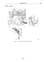
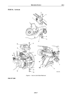
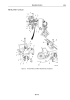
Remove two nuts (Figure 3, Item 5), lockwashers (Figure 3, Item 4), and screws (Figure 3, Item 3) from two
upper torque rod brackets (Figure 3, Item 1) and upper torque rod plates (Figure 3, Item 6). Upper torque rod
brackets will remain attached to torque rods (Figure 3, Item 2). Discard lockwashers.
12.
Remove two nuts (Figure 3, Item 14), lockwashers (Figure 3, Item 13), screws (Figure 3, Item 11), and right
and left upper spring brackets (Figure 3, Item 18) from left and right lead springs (Figure 3, Item 15) and dowel
pin (Figure 3, Item 16) on rear axle (Figure 3, Item 12). Discard lockwashers.
13.
Remove spring seat wear pads (Figure 3, Item 17) from right and left upper spring brackets
(Figure 3, Item 18).
NOTE
Assistant will help with Steps (14) through (15).
14.
Raise hydraulic jack and remove jack stands (Figure 3, Item 6) from rear axle (Figure 3, Item 12).
15.
Remove rear axle (Figure 3, Item 12) from vehicle.
TM 9-2320-272-23-3
0414
0414-6
Back to Top

