TM-9-2320-272-23-3 - Page 625 of 1469
INSTALLATION - Continued
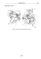
11.
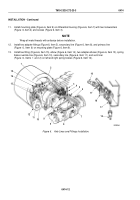
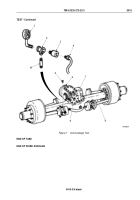
Install mounting plate (Figure 6, Item 9) on differential housing (Figure 6, Item 7) with two lockwashers
(Figure
6, Item 4) and screws (Figure 6, Item 3).
NOTE
Wrap all male threads with antiseize before installation.
12.
Install two adapter fittings (Figure 6, Item 5), secondary line (Figure 6, Item 8), and primary line
(Figure
6,
Item
6) on mounting plate (Figure 6, Item 9).
13.
Install tee fitting (Figure 6, Item 15), elbow (Figure 6, Item 14), two adapter elbows (Figure 6, Item 13), spring
brake override line (Figure 6, Item 10), secondary line (Figure 6, Item 11), and vent liner
(Figure
6,
Items
1
and
2) on left and right spring brakes (Figure 6, Item 12).
M7092DAA
4
7
8
9
10
16
17
18
17
16
11
12
13
14
15
5
6
5
3
2
1
Figure 6.
Axle Lines and Fittings Installation.
TM 9-2320-272-23-3
0414
0414-12
Back to Top

