TM-9-2320-272-23-3 - Page 629 of 1469
TEST
1.
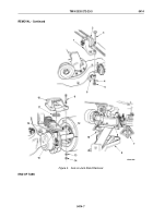
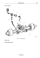
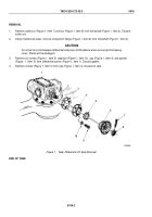
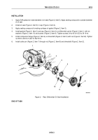
Remove breather (Figure 1, Item 5) from axle housing (Figure 1, Item 8).
2.
Install nipple (Figure 1, Item 10) and tee (Figure 1, Item 2) on axle housing (Figure 1, Item 8).
3.
Install air pressure gauge (Figure 1, Item 1) and quick-disconnect coupling (Figure 1, Item 3) on tee
(Figure
1, Item 2).
CAUTION
Do not allow air pressure to exceed 15 psi (103 kPa). Seals will be damaged if air pressure
exceeds 15 psi (103 kPa).
4.
Connect air supply hose (Figure 1, Item 4) to quick-disconnect coupling (Figure 1, Item 3).
5.
Turn on air supply and observe air pressure gauge (Figure 1, Item 1). When air pressure reaches 8 psi
(55
kPa), disconnect air supply hose (Figure 1, Item 4). Begin timing for a period of 45 seconds. After
45
seconds, check air gauge reading.
6.
If air gauge reading indicates leakage of 5 psi (35 kPa) or greater, perform corrective action.
NOTE
Perform Steps (7) through (11) if corrective action is required.
7.
Tighten all axle housing (Figure 1, Item 8) and differential carrier (Figure 1, Item 9) nuts and screws.
8.
Reconnect air supply hose (Figure 1, Item 4) to quick-disconnect coupling (Figure 1, Item 3) and turn on air
supply. When air pressure reaches 8 psi (55 kPa), disconnect air supply hose.
9.
Apply soapsuds around front oil seal cover (Figure 1, Item 6), rear oil seal cap (Figure 1, Item 7), base of
differential carrier (Figure 1, Item 9), and axle housing (Figure 1, Item 8). Air bubbles indicate defective or
missing sealing compound. Remove front oil seal cover, rear oil seal cap, or differential carrier and reseal
(WP
0407) , (WP
0418) , or (WP
0419).
10.
Remove quick-disconnect coupling (Figure 1, Item 3), air pressure gauge (Figure 1, Item 1), tee
(Figure
1,
Item
2), and nipple (Figure 1, Item 10) from axle housing (Figure 1, Item 8).
11.
Install breather (Figure 1, Item 5) on axle housing (Figure 1, Item 8).
TM 9-2320-272-23-3
0415
0415-2
Back to Top

