TM-9-2320-272-23-4 - Page 1261 of 1393
INSTALLATION
1.
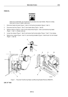
Install heater pump adapter (Figure 2, Item 5) in port (Figure 2, Item 9).
2.
Install adapter (Figure 2, Item 7) and heater pump elbow (Figure 2, Item 8) in heater pump (Figure 2, Item 6).
3.
Install heater pump (Figure 2, Item 6) on pump bracket (Figure 2, Item 3) with clamp (Figure 2, Item 4).
4.
Install wire (Figure 2, Item 16) on terminal stud (Figure 2, Item 15) with lockwasher (Figure 2, Item 17) and nut
(Figure 2, Item 18).
5.
Install ground wire (Figure 2, Item 13) on terminal stud (Figure 2, Item 14) with lockwasher
(Figure
2,
Item
12) and nut (Figure 2, Item 11).
6.
Install pump outlet hose (Figure 2, Item 23) on heater pump elbow (Figure 2, Item 5) and tighten clamp
(Figure
2,
Item
20).
7.
Install manifold inlet hose (Figure 2, Item 21) on heater pump elbow (Figure 2, Item 8) and tighten clamp
(Figure
2,
Item
19).
8.
Open two engine coolant heater drain valves (Figure 2, Item 22).
9.
Open water manifold drain valve (Figure 2, Item 1) and coolant outlet drain valve (Figure 2, Item 2).
10.
Close toolbox door (Figure 2, Item 10).
TM 9-2320-272-23-4
0752
0752-4
Back to Top


