TM-9-2320-272-23-4 - Page 235 of 1393
REMOVAL - Continued
3.
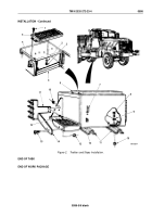
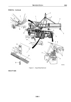
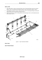
Disconnect four wires (Figure 3, Item 10) from each of two rear composite lights (Figure 3, Item 5). Tag wires
(Figure 3, Item 10) for installation.
4.
Remove eight locknuts (Figure 3, Item 7), screws (Figure 3, Item 9), and wire clamps (Figure 3, Item 8) from
cargo body (Figure 3, Item 4). Discard locknuts.
5.
Wrap two utility chains (Figure 3, Item 3) around subframe beam (Figure 3, Item 12) and fasten hooks
(Figure
3,
Item
18) over utility chains (Figure 3, Item 3).
6.
Attach lifting device (Figure 3, Item 2) to center of utility chains (Figure 3, Item 3).
WARNING
•
Lifting device must have a weight capacity greater than the weight of the truck bed. Failure
to comply may result in damage to equipment, injury, or death to personnel.
•
All personnel must stand clear during lifting operations. A snapped cable, or swinging or
shifting load, may occur. Failure to comply may result in injury or death to personnel.
NOTE
Mechanic will handle one guide line and direct hoisting operation. Assistant will handle other
guide line. Second assistant will operate lifting device.
7.
Connect two guide lines (Figure 3, Item 17) to front and rear lashing hooks (Figure 3, Item 1).
8.
Lift cargo body clear of frame (Figure 3, Item 6) and place on four shop stands (Figure 3, Item 16).
9.
Disconnect lifting device (Figure 3, Item 2), two utility chains (Figure 3, Item 3), and guide lines
(Figure
3,
Item
17) from cargo body (Figure 3, Item 4).
NOTE
Extra-long wheelbase models (M927/A1/A2, M928/A1/A2) utilize four wood sills, 20 washers,
and 20 screws.
10.
Remove ten locknuts (Figure 3, Item 15), lockwashers (Figure 3, Item 14), screws (Figure 3, Item 13), and two
wood sills (Figure 3, Item 11) from cargo bed (Figure 3, Item 12). Discard locknuts, lockwashers, and
wood
sills.
TM 9-2320-272-23-4
0588
0588-4
Back to Top

