TM-9-2320-272-23-4 - Page 239 of 1393
INSTALLATION - Continued
6.
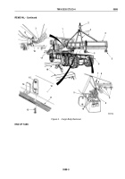
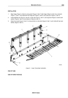
Lower cargo body (Figure 5, Item 3) onto frame (Figure 5, Item 11) while using a drift pin to align two front
upper holddown brackets (Figure 5, Item 5) to lower holddown brackets (Figure 5, Item 6), and four intermediate
holddown brackets (Figure 5, Item 13) to lower holddown brackets (Figure 5, Item 14).
7.
Place four outer support springs (Figure 5, Item 10) over inner support springs (Figure 5, Item 7), and position
under lower holddown brackets (Figure 5, Item 6), and install with four screws (Figure 5, Item 4), washers
(Figure 5, Item 9), and locknuts (Figure 5, Item 8). Tighten locknuts (Figure 5, Item 8) until length of springs
(Figure 5, Items 7 and 10) are 6.75 in. ± 0.06 in. (171.45 mm ± 1.5 mm).
NOTE
Extra-long wheelbase models (M927/A1/A2, M928/A1/A2) utilize six intermediate holddown
brackets, 12 screws, and 12 locknuts.
8.
Place four screws (Figure 5, Item 12) through intermediate holddown brackets (Figure 5, Item 13) and lower
holddown brackets (Figure 5, Item 14), and install four locknuts (Figure 5, Item 15).
9.
Disconnect lifting device (Figure 5, Item 1), utility chains (Figure 5, Item 2), and guide lines from cargo body
(Figure 5, Item 3).
10.
Connect four wires (Figure 5, Item 19) to connectors (Figure 5, Item 20) on each of two composite lights
(Figure
5, Item 21).
11.
Install eight wire clamps (Figure 5, Item 17) on cargo body (Figure 5, Item 3) with eight screws
(Figure 5, Item 18) and locknuts (Figure 5, Item 16).
TM 9-2320-272-23-4
0588
0588-8
Back to Top


