TM-9-2320-272-23-4 - Page 317 of 1393
DISASSEMBLY
1.
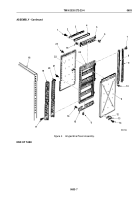
Remove 16 screws (Figure 2, Item 17), hinge (Figure 2, Item 19), and seal (Figure 2, Item 20) from panel frame
(Figure 2, Item 24). Discard seal.
2.
Remove 27 screws (Figure 2, Item 7), retainer (Figure 2, Item 9), and seal (Figure 2, Item 8) from panel frame
(Figure 2, Item 24). Discard seal.
3.
Remove ten screws (Figure 2, Item 1), retainers (Figure 2, Items 2 and 3), and seal (Figure 2, Item 4) from
channel (Figure 2, Item 5). Discard seal.
4.
Remove 18 rivets (Figure 2, Item 6), 20 screws (Figure 2, Item 16), and channels
(Figure 2, Items 5 and 15) from outer skin (Figure 2, Item 11) and inner skin (Figure 2, Item 22). Discard rivets.
5.
Remove two screws (Figure 2, Item 14), strap (Figure 2, Item 13), and spacer plate (Figure 2, Item 12) from
outer skin (Figure 2, Item 11).
NOTE
•
Perform Steps (6) and (7) only if skins are to be replaced. See CLEANING AND
INSPECTION.
•
Assistant will help with Steps (6) and (7).
6.
Remove 12 rivets (Figure 2, Item 10) and outer skin (Figure 2, Item 11) from panel frame
(Figure 2, Item 24). Discard rivets.
7.
Remove 30 screws (Figure 2, Item 23), 18 screws (Figure 2, Item 21), and inner skin
(Figure 2, Item 22) from panel frame (Figure 2, Item 24).
TM 9-2320-272-23-4
0603
0603-4
Back to Top

