TM-9-2320-272-23-4 - Page 325 of 1393
INSTALLATION
NOTE
Perform Step (1) if installing new counterbalance cable.
1.
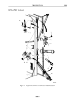
Remove eye of turnbuckle (Figure 3, Item 10) from replacement cable end (Figure 3, Item 9).
2.
Thread cable (Figure 3, Item 8) through two cable guides (Figure 3, Item 16) and connect to turnbuckle
(Figure
3,
Item
10).
3.
Align lower folding arm (Figure 3, Item 12) with holes in corner post (Figure 3, Item 11) and install lower roller
(Figure 3, Item 15) on folding arm (Figure 3, Item 12) with pin (Figure 3, Item 13) and cotter pin
(Figure
3,
Item
14). Ensure cable (Figure 3, Item 8) is behind lower roller.
4.
Install upper roller (Figure 3, Item 7) on mounting plate (Figure 3, Item 6) with pin (Figure 3, Item 5) and cotter
pin (Figure 3, Item 4). Ensure cable (Figure 3, Item 8) is behind upper roller.
5.
Install cable clevis (Figure 3, Item 1) on drop arm (Figure 3, Item 3) with pin (Figure 3, Item 2) and cotter pin
(Figure 3, Item 17).
TM 9-2320-272-23-4
0604
0604-4
Back to Top


