TM-9-2320-272-23-4 - Page 453 of 1393
INSTALLATION (M934A1/A2)
NOTE
Wrap male threads with antiseize tape prior to installation.
1.
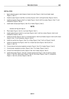
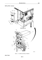
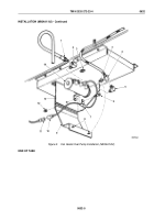
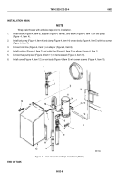
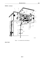
Install elbows (Figure 2, Item 2) and (Figure 2, Item 5) on fuel pump (Figure 2, Item 14).
2.
Install fuel pump (Figure 2, Item 14) and clamp (Figure 2, Item 7) with fuel pump lead (Figure 2, Item 10) on
hinge plate (Figure 2, Item 13) with two screws (Figure 2, Item 6) and locknuts (Figure 2, Item 12).
3.
Connect input line (Figure 2, Item 1) to elbow (Figure 2, Item 2).
4.
Connect output line (Figure 2, Item 4) to elbow (Figure 2, Item 5).
5.
Connect fuel pump lead (Figure 2, Item 10) to harness lead (Figure 2, Item 11).
6.
Close access door (Figure 2, Item 9) and tighten two locking studs (Figure 2, Item 8) in turnbuckles
(Figure
2,
Item
3).
TM 9-2320-272-23-4
0632
0632-4
Back to Top


