TM-9-2320-272-23-4 - Page 447 of 1393
INSTALLATION
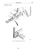
1.
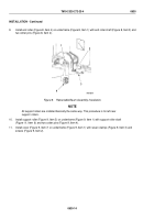
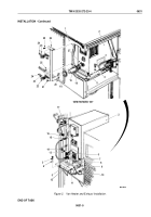
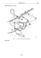
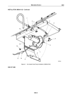
Apply antiseizing tape to male threads of heater fuel valve (Figure 2, Item 6) and heater nipple
(Figure
2,
Item
7).
2.
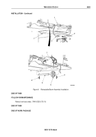
Install two seals (Figure 2, Item18) on van body (Figure 2, Item 1) with eight screws (Figure 2, Item 5).
3.
Install two brackets (Figure 2, Item 5) on heater (Figure 2, Item 2) with five screws (Figure 2, Item 11) and
lockwashers (Figure 2, Item 9).
4.
Install heater exhaust pipe (Figure 2, Item 19) on heater (Figure 2, Item 2).
NOTE
Assistant will help with Step (5).
5.
Place heater (Figure 2, Item 2) in van body (Figure 2, Item 1).
6.
Install bracket (Figure 2, Item 5) on van body (Figure 2, Item 1) with four screws (Figure 2, Item 3) and
lockwashers (Figure 2, Item 4).
7.
Install ground strap (Figure 2, Item 10) on bracket (Figure 2, Item 5) and heater (Figure 2, Item 2) with screws
(Figure 2, Item 11) and lockwasher (Figure 2, Item 9).
8.
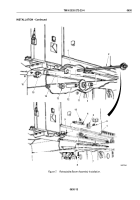
Install fuel overflow line (Figure 2, Item 12) on fitting (Figure 2, Item 7) with nut (Figure 2, Item 8).
9.
Install fuel receptacle line (Figure 2, Item 14) on heater fuel valve (Figure 2, Item 6) with nut
(Figure
2,
Item
13).
10.
Connect external fuel pump receptacle connector (Figure 2, Item 15) to heater (Figure 2, Item 2).
11.
Connect power receptacle connector (Figure 2, Item 17) to heater (Figure 2, Item 2).
12.
Connect room thermostat connector (Figure 2, Item 16) to heater (Figure 2, Item 2).
13.
Install exhaust pipe (Figure 2, Item 26) on heater exhaust pipe (Figure 2, Item 19) with two clamps
(Figure
2,
Item
22), eight screws (Figure 2, Item 25), two screws (Figure 2, Item 21), lockwashers
(Figure
2,
Item
23), and nuts (Figure 2, Item 24).
TM 9-2320-272-23-4
0631
0631-4
Back to Top

