TM-9-2320-272-23-4 - Page 437 of 1393
INSTALLATION
1.
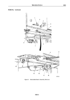
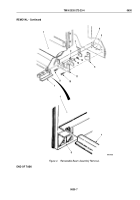
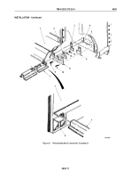
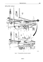
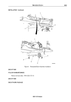
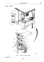
Install seal (Figure 6, Item 6), gaskets (Figure 6, Items 2 and 3), and retainer (Figure 6, Item 11) on underframe
(Figure
6,
Item
4) with seven screws (Figure 6, Item 10), two screws (Figure 6, Item 9), washers
(Figure
6,
Item
12), and locknuts (Figure 6, Item 13).
CAUTION
Install retractable beam slowly into underframe. Failure to do so may result in damage
to
equipment.
2.
Slide retractable beam (Figure 6, Item 7) under side panel (Figure 6, Item 1) and install in underframe
(Figure
6,
Item
4) at channel (Figure 6, Item 5).
3.
Install retractable beam (Figure 6, Item 7) by welding retractable beam (Figure 6, Item 7) to side panel
(Figure
6,
Item
1) and side panel support (Figure 6, Item 8) (TM 9-237).
TM 9-2320-272-23-4
0630
0630-10
Back to Top


