TM-9-2320-272-23-4 - Page 431 of 1393
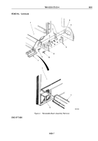
REMOVAL - Continued
NOTE
Left and right retractable beam drive shafts and locks are replaced the same. This procedure
is for the left retractable beam drive shaft and lock.
4.
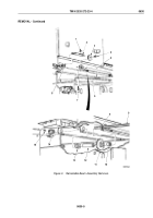
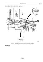
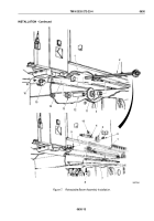
Remove locknut (Figure 3, Item 1) and lock (Figure 3, Item 2) from underframe stud (Figure 3, Item 8).
Discard
locknut.
5.
Remove screw (Figure 3, Item 4), pawl (Figure 3, Item 3), and lock (Figure 3, Item 2) from underframe
(Figure
3,
Item
5).
6.
Remove 30 screws (Figure 3, Item 7) and five covers (Figure 3, Item 6) from underframe (Figure
3,
Item
5).
7.
Remove four setscrews (Figure 3, Item 15) from bushings (Figure 3, Item 14).
CAUTION
Do not bend or strain ratchet shaft during removal. Doing so may result in damage
to
equipment.
NOTE
•
Remove all nicks, burrs, and corrosion from ratchet shaft and lubricate before removal.
•
Direct assistant to catch ratchet shaft components under van body during removal.
8.
Slowly pull ratchet shaft (Figure 3, Item 9) and remove four bushings (Figure 3, Item 14), nine bushings
(Figure
3,
Item
13), spacers (Figure 3, Item 12), sprockets (Figure 3, Item 11), and five spacers
(Figure
3,
Item
10) from underframe (Figure 3, Item 5).
TM 9-2320-272-23-4
0630
0630-4
Back to Top


