TM-9-2320-272-23-4 - Page 441 of 1393
INSTALLATION - Continued
9.
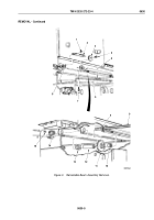
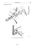
Install end roller (Figure 8, Item 4) on underframe (Figure 8, Item 1) with end roller shaft (Figure 8, Item 3) and
two cotter pins (Figure 8, Item 2).
M4018DAA
2
1
3
4
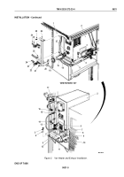
Figure 8.
Retractable Beam Assembly Installation.
NOTE
All support rollers are installed basically the same way. This procedure is for left-rear
support
rollers.
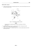
10.
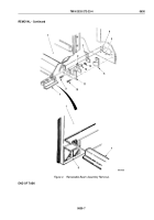
Install support roller (Figure 9, Item 5) on underframe (Figure 9, Item 1) with support roller shaft
(Figure
9,
Item
6) and two cotter pins (Figure 9, Item 4).
11.
Install cover (Figure 9, Item 7) on underframe (Figure 9, Item 1) with seven clamps (Figure 9, Item 3) and
screws (Figure 9, Item 2).
TM 9-2320-272-23-4
0630
0630-14
Back to Top

