TM-9-2320-272-23-4 - Page 681 of 1393
REMOVAL
WARNING
•
Lifting device must have a weight capacity greater than the combined weight of the truck
bed. Failure to comply may result in damage to equipment, injury, or death to personnel.
•
All personnel must stand clear during lifting operations. A snapped cable, or swinging or
shifting load, may occur. Failure to comply may result in injury or death to personnel.
•
Solvent cleaning compound is flammable and toxic. Do not use near open flame and
always have a fire extinguisher nearby when solvents are used. Use only in well-
ventilated places, wear protective clothing, and dispose of cleaning rags in approved
container. Failure to comply may result in damage to equipment, injury, or death to
personnel.
NOTE
The left and right side body mounts are replaced the same. This procedure covers the left
side body mounts.
1.
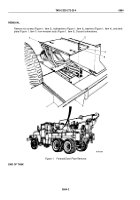
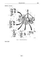
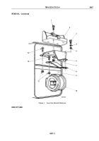
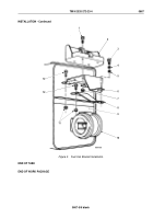
Remove four locknuts (Figure 1, Item 12), two U-bolts (Figure 1, Item 11), and wood blocks (Figure 1, Item 3)
from frame rail (Figure 1, Item 4) and wrecker body (Figure 1, Item 1). Discard locknuts.
2.
Remove four locknuts (Figure 1, Item 14) and two U-bolts (Figure 1, Item 13) from frame rail
(Figure 1, Item 4) and wrecker body (Figure 1, Item 1). Discard locknuts.
3.
Remove four locknuts (Figure 1, Item 16), two U-bolts (Figure 1, Item 15), and four wood blocks
(Figure 1, Item 3) from frame rail (Figure 1, Item 4) and wrecker body (Figure 1, Item 1). Discard locknuts.
4.
Remove four locknuts (Figure 1, Item 2), four mounting screws (Figure 1, Item 17), two plates
(Figure 1, Item 18), and four wood blocks (Figure 1, Item 3) from frame rail (Figure 1, Item 4) and wrecker body
(Figure 1, Item 1). Discard locknuts.
5.
Remove 16 locknuts (Figure 1, Item 8), screws (Figure 1, Item 9), and two brackets
(Figure 1, Item 10) from frame rail (Figure 1, Item 4). Discard locknuts.
6.
Attach two guide lines (Figure 1, Item 5) and utility chains (Figure 1, Item 7) to wrecker body
(Figure 1, Item 1) and lifting device (Figure 1, Item 6) to utility chains.
NOTE
Two assistants will help with Steps (7) and (8).
7.
Remove wrecker body (Figure 1, Item 1) from frame rail (Figure 1, Item 4) and lower onto support stands.
8.
Remove lifting device (Figure 1, Item 6), two chains (Figure 1, Item 7), and guide lines (Figure 1, Item 5) from
wrecker body (Figure 1, Item 1).
TM 9-2320-272-23-4
0666
0666-2
Back to Top

