TM-9-2320-272-23-4 - Page 683 of 1393
INSTALLATION
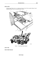
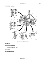
1.
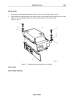
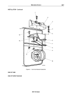
Attach two guide lines (Figure 2, Item 5) and utility chains (Figure 2, Item 7) to wrecker body
(Figure 2, Item 1) and lifting device (Figure 2, Item 6) to utility chains.
2.
Raise wrecker body (Figure 2, Item 1) from support stands and position on frame rail (Figure 2, Item 4). Ensure
mounting holes of frame rail and wrecker body are aligned.
3.
Install two wood blocks (Figure 2, Item 3) on frame rail (Figure 2, Item 4) and wrecker body (Figure 2, Item 1)
with two U-bolts (Figure 2, Item 11) and four locknuts (Figure 2, Item 12).
4.
Install two U-bolts (Figure 2, Item 13) on frame rail (Figure 2, Item 4) and wrecker body (Figure 2, Item 1) with
four locknuts (Figure 2, Item 14).
5.
Install four wood blocks (Figure 2, Item 3) on frame rail (Figure 2, Item 4) and wrecker body (Figure 2, Item 1)
with two U-bolts (Figure 2, Item 15) and four locknuts (Figure 2, Item 16).
6.
Install two plates (Figure 2, Item 18) and four wood blocks (Figure 2, Item 3) on frame rail (Figure 2, Item 4)
and wrecker body (Figure 2, Item 1) with four mounting screws (Figure 2, Item 17) and locknuts
(Figure 2, Item 2).
7.
Install two brackets (Figure 2, Item 10) on frame rail (Figure 2, Item 4) with 16 screws (Figure 2, Item 9) and
locknuts (Figure 2, Item 8).
8.
Remove lifting device (Figure 2, Item 6), two chains (Figure 2, Item 7), and guide lines (Figure 2, Item 5) from
wrecker body (Figure 2, Item 1).
TM 9-2320-272-23-4
0666
0666-4
Back to Top

