TM-9-2320-272-23-4 - Page 847 of 1393
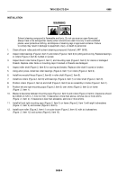
INSTALLATION
1.
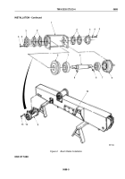
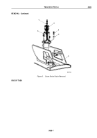
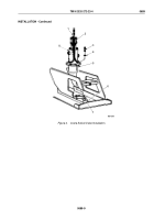
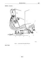
Install utility chain (Figure 4, Item 2) and hoist hook (Figure 4, Item 1) on hydraulic swivel valve
(Figure
4,
Item
8).
WARNING
All personnel must stand clear during lifting operations. A snapped chain, or shifting or
swinging load, may result in injury to personnel. Failure to comply may result in injury or death
to personnel.
NOTE
Assistant will help with Step (2).
2.
Align valve guide pins (Figure 4, Item 5) on swivel valve (Figure 4, Item 8) with slots (Figure 4, Item 7) in
turntable (Figure 4, Item 6) and install with six lockwashers (Figure 4, Item 4) and screws (Figure 4, Item 3).
Tighten screws 44 to 61 lb-ft (60 to 83 N·m).
3.
Remove hoist (Figure 4, Item 1) hook and utility chain (Figure 4, Item 2) from hydraulic swivel valve
(Figure
4,
Item
8).
TM 9-2320-272-23-4
0689
0689-8
Back to Top

