TM-9-2320-272-23-4 - Page 849 of 1393
INSTALLATION - Continued
4.
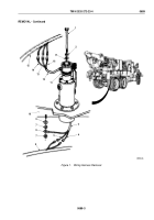
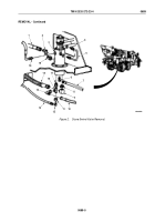
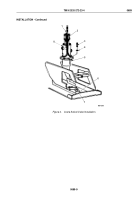
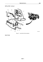
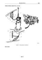
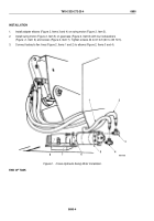
Install adapter fitting (Figure 5, Item 17) on swivel valve (Figure 5, Item 1) and adapter fitting
(Figure
5,
Item
19) on adapter fitting.
5.
Connect hydraulic tube (Figure 5, Item 3) to swivel valve (Figure 5, Item 1) and elevating cylinder tee
(Figure
5,
Item
2).
6.
Connect hydraulic lines (Figure 5, Items 16 and 18) to hydraulic swivel valve (Figure 5, Item 1).
7.
Install adapter fittings (Figure 5, Items 4, 6, 7, 9, 10, 12, 14, and 15) on lower end of hydraulic swivel valve
(Figure 5, Item 1).
8.
Connect hydraulic lines (Figure 5, Items 5, 8, 11, and 13) to fittings on lower end of hydraulic swivel valve
(Figure 5, Item 1).
TM 9-2320-272-23-4
0689
0689-10
Back to Top


